
Forum Replies Created
-
AuthorPosts
-
Chris Hood
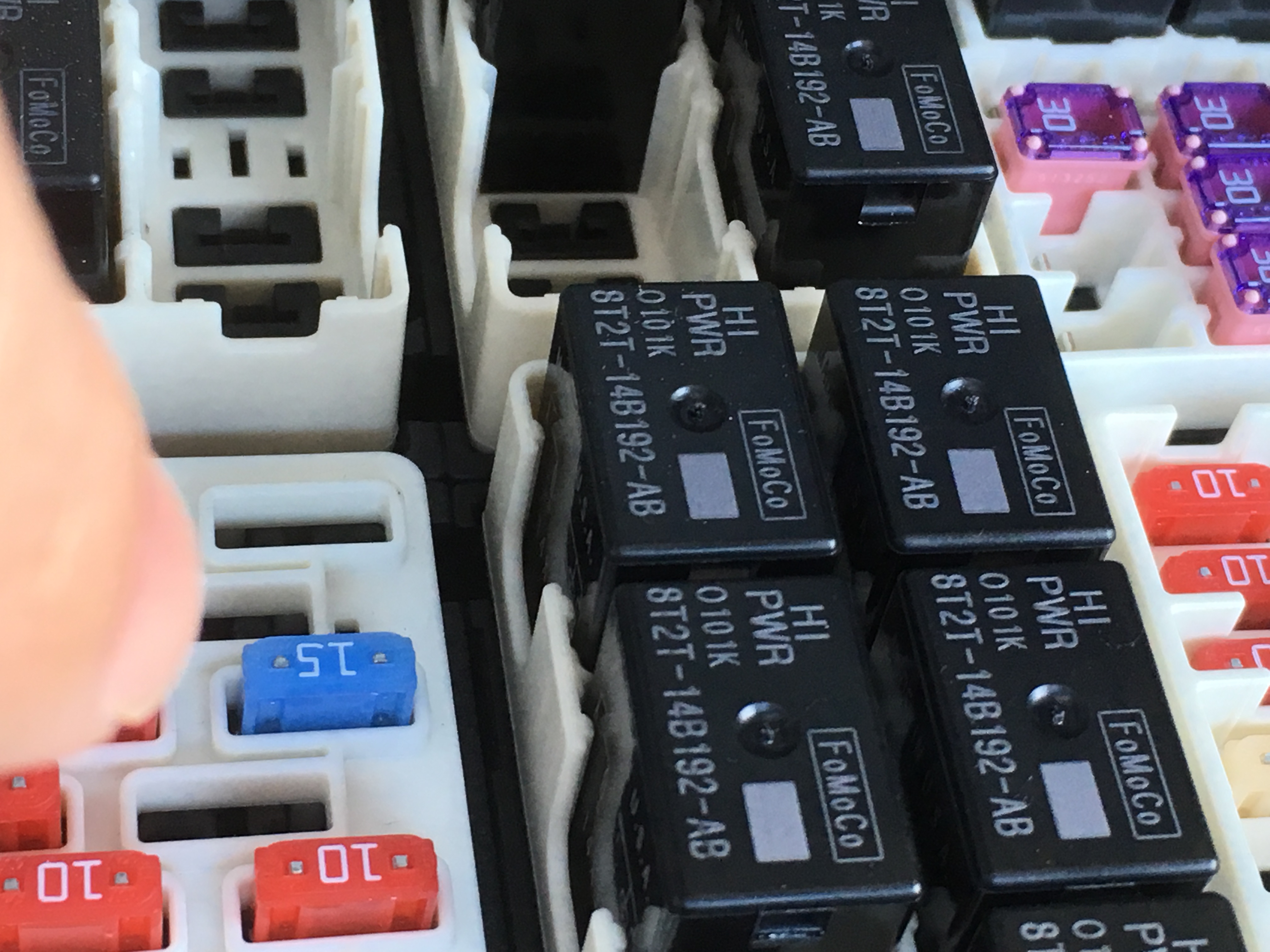
ModeratorThe 2017 F-150 has a new style computer, this includes the Raptor. On these units we had to add a 12V power supply. This will come from a supplied fuse tap that will go to Fuse slot 99 in the under hood fuse box. It is important that it goes to fuse 99 because the box needs its power running and during cranking. Below are a couple pictures of the 1st test units, the production units will be different only in that they will have weather pack connectors.
https://www.jmschip.com/content/BoostMAX/2017_Raptor/2017F150_JMSFuseTapInstall2.JPG
https://www.jmschip.com/content/BoostMAX/2017_Raptor/2017F150_JMSFuseTapInstalled_fuse991.JPG
https://www.jmschip.com/content/BoostMAX/2017_Raptor/2017F150_JMSFuseTapInstall3.JPG
ModeratorGround activation of LaunchMAX & GROUND activation of Accessory (Two Step, etc):
1 – Connect Relay pin 85 to key on +12v power.
2 – Connect Relay pin 86 to Pin 7 / Blue wire from the JMS LauchMAX harness.
3 – Connect Relay pin 87 to the ground trigger connection for the accessory
4 – Connect Relay pin 30 to vehicle ground.Ground activation of LaunchMAX & Positive activation of Accessory (Two Step, etc):
1 – Connect Relay pin 85 to key on +12v power.
2 – Connect Relay pin 86 to Pin 7 / Blue wire from the JMS LauchMAX harness.
3 – Connect Relay pin 87 to the positive trigger connection for the accessory
4 – Connect Relay pin 30 to key on +12V power.
Positive activation of LaunchMAX & Positive activation of Accessory (Two Step, etc):
1 – Connect Relay pin 85 to Pin 8 / Red wire from the JMS LaunchMAX harness.
2 – Connect Relay pin 86 to ground
3 – Connect Relay pin 87 to the positive trigger connection for the accessory
4 – Connect Relay pin 30 to key on +12V power.Positive activation of LaunchMAX & GROUND activation of Accessory (Two Step, etc):
1 – Connect Relay pin 85 to Pin 8 / Red from the JMS LaunchMAX harness.
2 – Connect Relay pin 86 to ground
3 – Connect Relay pin 87 to the ground trigger connection for the accessory
4 – Connect Relay pin 30 to vehicle ground.ModeratorThe, soon to be released, Plug and Play Version includes a wire that can be used for activation of a relay. That wire takes the place of the red wire in the positive activation T-brake wiring with whichever activation (+ or -) your accessory happens to use.
ModeratorAfter further research I have found that the 2015 and up 3.5 Non-Ecoboost engine in the F-150 has the same pin numbers as the 5.0 F-150 to wire in the LaunchMAX.
The 2015 and up 2.7 EcoBoost uses the same pins as the 2015-up 3.5 Ecoboost to wire in the LaunchMAX.
-Charlie
-
AuthorPosts